Programmable Pipeline의 토대,
스칼라 중심 GPU → SIMD Lane 재구성

그래픽카드의 한계

 2000년대 초반의 GPU는 FFP(Fixed Function Pipeline)중심이었고, 지금처럼 복잡한 셰이더 기반 렌더링이 불가능했습니다. VRAM 용량도 32~64MB 수준이라 SSAA나 고급 조명 기법을 적용하기 어려웠죠. 이 글에서는 당시 GPU의 한계를 살펴보고, 어떻게 SIMD 기반의 Programmable Pipeline 으로 발전했는지 정리합니다.


MSAA (Multi-Sampling Anti-Aliasing)

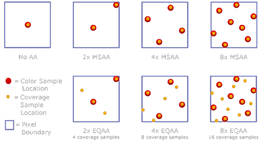
MSAA vs EQAA 샘플 패턴 비교 이미지

Pixel Boundary

한 픽셀을 크게 확대한 사각형 틀. (픽셀은 점이 아니라 “면적”을 가진 사각형입니.)

Color Sample Location

픽셀 내부의 특정 지점(Point)에서 실제 색상(Color)을 샘플링하는 위치. 여러 Color Sample을 블렌딩하여 최종 픽셀 색을 만든다.

Coverage Sample Location

폴리곤이 픽셀을 얼마나 덮고 있는지(Coverage) 판단하는 지점. 각 샘플이 폴리곤 내부면 1, 외부면 0에 해당하며, 이를 평균내어 블렌딩 가중치(강도)로 사용한다. Color Sample보다 계산 비용이 훨씬 낮다.


 초기 GPU의 VRAM 용량이 32 ~ 64MB 하던 시절에는 픽셀 단위로 복잡한 처리를 수행할 수 없었습니다. 그래서 이미지 전체를 더 높은 해상도로 여러 번 렌더링하는 SSAA(Super-Sampling Anti-Aliasing)을 다운 샘플링을 하는 방식이 유일한 선택지였습니다. 해당 방식은 해상도 배율 x 샘플 수 만큼의 비용증가가 있었고, 이는 픽셀 셰이딩, 텍스쳐 샘플링, ROP(Blend / Depth / Color Write) 등 '픽셀 이후 단계'의 비용을 전부 O(S) 수준으로 폭증시켰습니다. 즉, 샘플 수만큼만 비용이 증가하는 것이 아니라, 렌더타겟 자체도 커지기 때문에 파이프라인의 대부분이 정비례로 비싸지는 구조였습니다.

 하지만 VRAM 용량이 어느정도 여유가 생기자, 픽셀 내부의 Color Sample과 Coverage Sample을 저장할 수 있는 구조가 가능해졌고, MSAA는 Pixel Shader는 한 번만 수행하고, Coverage Test와 Color Resolve만 샘플 수에 따라 반복하는 방식으로 SSAA 대비 큰 폭의 최적화를 달성했습니다.


Fixed Function Pipeline > Programmable Pipeline 의 과도기

FFP(Fixed Function Pipeline)

  • Transform & Lighting
  • Texture Stage State 기반 2~3단 텍스처 처리
  • 멀티패스 조명
  • DOT3 Bump Mapping(FFP LOD 바탕)
  • Lightmap 기반의 Static Lighting
  • UI, HUD, 간단한 머터리얼 > FFP로 렌더링

하지만 UE2 후반 버전은...

Programmable Pipeline 일부 적용

  • Shader-driven Material Effects
  • Normal Mapping
  • Specular Mask
  • Detail Normal Layer
  • Color Modulation
  • Hardware Skinning
  • NVIDIA/ATI 전용 Shader Path

이것이 가능해진 이유는 GPU의 주요한 변화 덕분.

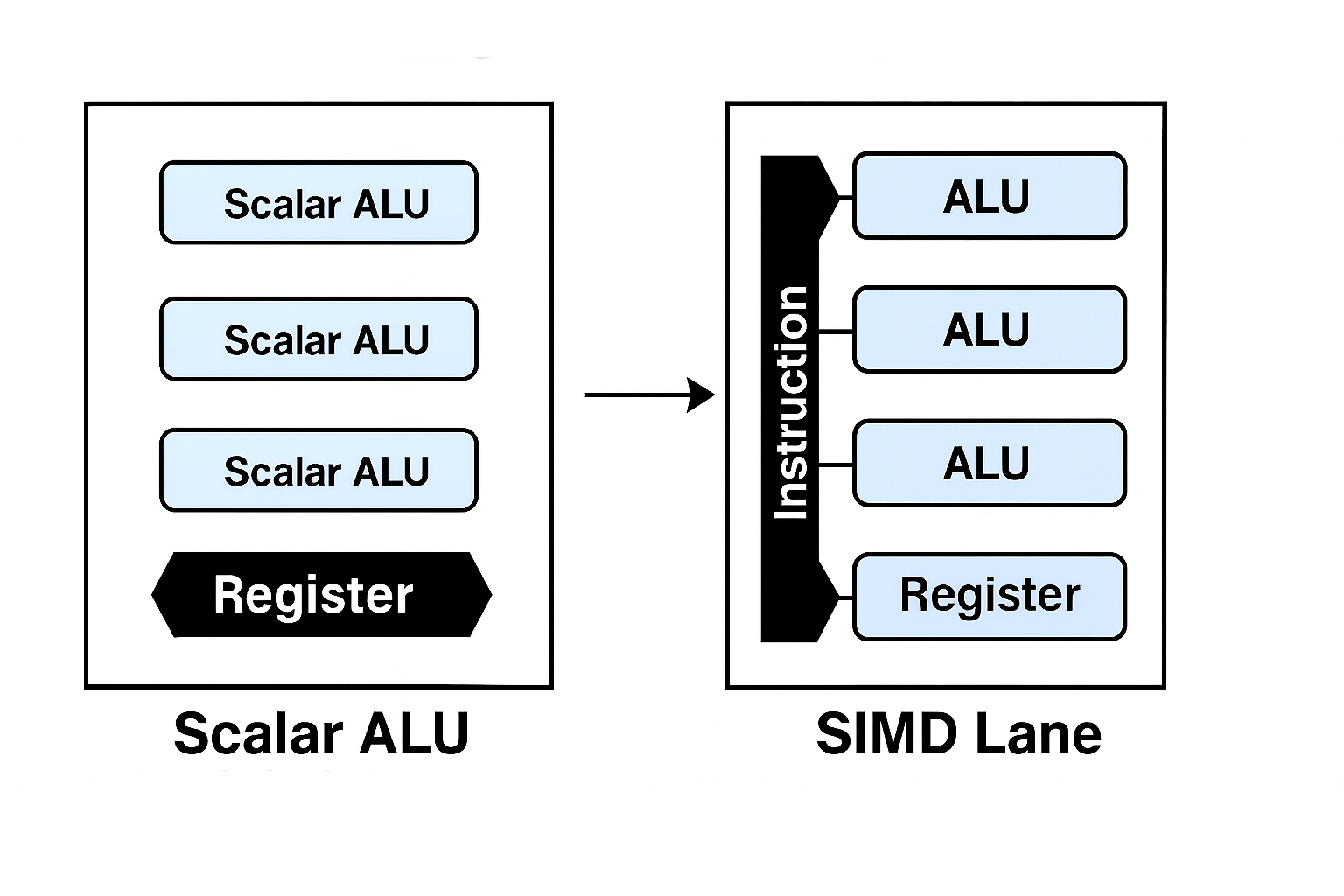
Scalar ALU vs SIMD Lane

기존

 Scalar ALU에 단순한 microcode 실행기를 사용하여 float4연산은 4개의 스칼라 연산을 순차적으로 연산하도록 실행, 단지 GPU에 Scalar ALU를 많이 담아서 단순 병렬처리를 수행했을 뿐.

SIMD(Single Instruction Multiple Data stream)의 등장

하나의 명령어(Single Instruction)를 Scalar ALU의 묶음인 SIMD Lane에 전달하여 연산에 사용될 Multi-Data를 레지스터/버퍼(L1/L2, GPR)에 담아 연산하도록 실행


다음글


UE2의 Overlay Shader와 초기 Post Process Effect

GPU의 역사 - 1 : FFP에서 SIMD까지그래픽카드의 한계 2000년대 초반의 GPU는 FFP(Fixed Function Pipeline)중심이었고, 지금처럼 복잡한 셰이더 기반 렌더링이 불가능했습니다. VRAM 용량도 32~64MB 수준이라 SSAA

chessire.tistory.com


GPU의 역사 - 2 : SIMD에서 SIMT로, Branch Divergence

GPU의 역사 - 1 : FFP에서 SIMD까지그래픽카드의 한계 2000년대 초반의 GPU는 FFP(Fixed Function Pipeline)중심이었고, 지금처럼 복잡한 셰이더 기반 렌더링이 불가능했습니다. VRAM 용량도 32~64MB 수준이라 SSAA

chessire.tistory.com

0. 개요

 요즘 레이트레이싱에 관련된 작업을 시작하게 되어 정리차원에서 블로깅하게 되었습니다. 현재는 TinyRaytracer를 마개조 중이었고, 이번 글은 깃헙의 TinyRaytracer를 기반으로 레이트레이싱 기법에 대해 간략하게 설명해보도록 하겠습니다. 최적화 기법은 추후에 다룰 예정입니다. 다른 포스팅에서 확인 부탁드립니다. (fresnel equation이 추가되었습니다.)


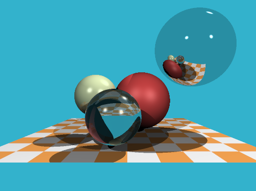
 TinyRaytracer를 간략하게 설명드리면 다음과 같이 세 단계로 구성되어 있습니다.

 - 카메라에서 레이를 캐스팅한다.

 -> 레이를 추적하여 레이와 충돌된 물체의 diffuse, specular, reflect, refract 컬러를 계산하여 더한다.

 -> ppm파일로 추출한다.


1. 요소

 - 객체

Light : 그저 빛

Material : 재질

Object : 화면에 표시할 객체, 여기서는 간단하게 표현하기 위해 sphere만을 사용


 - 기능

render

 - ppm파일에 해당 씬을 그려주는 함수

cast_ray

 - 이를 캐스팅하고 충돌한 Object와 Light를 참조하여 Material 값을 계산한 후, 컬러값을 반환

scene_intersect

 - 레이를 씬과 충돌연산하여 hit point, hit normal, material 값을 반환

reflect

 - 물체에 반사된 레이의 컬러값을 반환

refract

 - 물체에 투과된 레이의 컬러값을 반환

fresnel

 - 레이의 입사각 및 물체의 Normal, 투과율에 따라 변하는 reflect와 refract의 비율을 반환
(이 부분은 tiny raytracer에는 없고, 퀄리티 업을 위하여 추가한 기능)


1. 객체 설명


 - Light

struct Light {
    Light(const Vec3f &p, const float i) : position(p), intensity(i) {}
    Vec3f position;
    float intensity;
};

Ambient light 입니다.


 - Material

struct Material {
    Material(const float r, const Vec4f &a, const Vec3f &color, const float spec) : refractive_index(r), albedo(a), diffuse_color(color), specular_exponent(spec) {}
    Material() : refractive_index(1), albedo(1,0,0,0), diffuse_color(), specular_exponent() {}
    float refractive_index;
    Vec4f albedo;
    Vec3f diffuse_color;
    float specular_exponent;
};

refractive_index : 투과율(1.0 : 공기, 1.3~1.5 : 유리구슬, 1.8 : 다이아몬드)

albedo : diffuse(x), specular(y), reflection(z), refraction(w)에 대한 0~1 수치입니다.


 - Object

struct Sphere {
	Vec3f center;
	float radius;
	Material material;

	Sphere(const Vec3f &c, const float r, const Material &m) : center(c), radius(r), material(m) {}

    bool ray_intersect(const Vec3f &orig, const Vec3f &dir, float &t0) const {
        Vec3f L = center - orig;
        float tca = L * dir;
        if (tca < 0) return false;
        float d2 = L*L - tca*tca;
        if (d2 > radius*radius) return false;
        float thc = sqrtf(radius*radius - d2);
        t0       = tca - thc;
		float t1 = tca + thc;
		if (t0 < 0) t0 = t1;
		if (t0 < 0) return false;
        return true;
    }
};

화면에 출력할 오브젝트입니다. 여기서는 편의상 구를 사용합니다.

ray_intersect함수의 경우, 레이의 original position, direction을 받아서 해당 오브젝트의 충돌검출(구와 직선의 충돌 알고리즘)과 함께 해당 오브젝트까지의 거리를 t0로 넘겨줍니다.


2. 기능 설명

 - render

void render(const std::vector<const sdf_model*> &models, const std::vector<Light> &lights) {
    const int   width    = 1024;
    const int   height   = 768;
    const float fov      = M_PI/3.;
    std::vector<Vec3f> framebuffer(width*height);

    #pragma omp parallel for
    for (size_t j = 0; j<height; j++) { // actual rendering loop
        for (size_t i = 0; i<width; i++) {
            float dir_x =  (i + 0.5) -  width/2.;
            float dir_y = -(j + 0.5) + height/2.;    // this flips the image at the same time
            float dir_z = -height/(2.*tan(fov/2.));
            framebuffer[i+j*width] = cast_ray(Vec3f(0,0,0), Vec3f(dir_x, dir_y, dir_z).normalize(), models, lights);
        }
    }

    std::ofstream ofs; // save the framebuffer to file
    ofs.open("./out.ppm",std::ios::binary);
    ofs << "P6\n" << width << " " << height << "\n255\n";
    for (size_t i = 0; i < height*width; ++i) {
        Vec3f &c = framebuffer[i];
        float max = std::max(c[0], std::max(c[1], c[2]));
        if (max > 1) c = c * (1. / max);
        for (size_t j = 0; j<3; j++) {
            ofs << (char)(255 * std::max(0.f, std::min(1.f, framebuffer[i][j])));
        }
    }
    ofs.close();
}

카메라에서 레이를 발사하여 frame buffer에 기록하고, 그 데이터를 ppm 파일에 저장합니다.


 - cast_ray

Vec3f cast_ray(const Vec3f &orig, const Vec3f &dir, const std::vector<Sphere> &spheres, const std::vector<Light> &lights, size_t depth=0) {
    Vec3f point, N;
    Material material;

    if (depth>4 || !scene_intersect(orig, dir, spheres, point, N, material)) {
        return Vec3f(0.2, 0.7, 0.8); // background color
    }

	Vec3f refract_color(0.f, 0.f, 0.f);
	// compute fresnel
	float kr;
	fresnel(dir, N, material.refractive_index, kr);
	// compute refraction if it is not a case of total internal reflection
	if (kr < 1) {
		Vec3f refract_dir = refract(dir, N, material.refractive_index).normalize();
		Vec3f refract_orig = refract_dir * N < 0 ? point - N * EPSILON : point + N * EPSILON;
		refract_color = cast_ray(refract_orig, refract_dir, models, lights, depth + 1);
	}

	Vec3f reflect_dir = reflect(dir, N).normalize();
	Vec3f reflect_orig = reflect_dir * N < 0 ? point - N * EPSILON : point + N * EPSILON; // offset the original point to avoid occlusion by the object itself
	Vec3f reflect_color = cast_ray(reflect_orig, reflect_dir, models, lights, depth + 1);

    float diffuse_light_intensity = 0, specular_light_intensity = 0;
    for (size_t i=0; i<lights.size(); i++) {
        Vec3f light_dir      = (lights[i].position - point).normalize();
        float light_distance = (lights[i].position - point).norm();

        Vec3f shadow_orig = light_dir*N < 0 ? point - N*EPSILON : point + N*EPSILON; // checking if the point lies in the shadow of the lights[i]
        Vec3f shadow_pt, shadow_N;
        Material tmpmaterial;
        if (scene_intersect(shadow_orig, light_dir, spheres, shadow_pt, shadow_N, tmpmaterial) && (shadow_pt-shadow_orig).norm() < light_distance)
            continue;

        diffuse_light_intensity  += lights[i].intensity * std::max(0.f, light_dir*N);
        specular_light_intensity += powf(std::max(0.f, -reflect(-light_dir, N)*dir), material.specular_exponent)*lights[i].intensity;
    }
    return material.diffuse_color * diffuse_light_intensity * material.albedo[0]
		+ Vec3f(1., 1., 1.)*specular_light_intensity * material.albedo[1]
		+ reflect_color * material.albedo[2] * kr
		+ refract_color * material.albedo[3] * (1 - kr);
}

레이를 발사하는 함수입니다. 먼저 장면에 충돌시켜 충돌된 위치(point)와 해당 point의 normal값을 구합니다. 그 후, 위 함수는 세 연산으로 나뉩니다.


첫번째는 레이 연산입니다. 레이 연산은 다시 세가지로 나뉘는데 fresnel equation, 반사(reflection), 투과(refraction입니다. 이 부분을 설명하기엔 길어지므로 아래의 각 파트에서 다루도록 하겠습니다.


두번째는 빛 연산입니다. 먼저 변수에 대한 설명을 진행하도록 하겠습니다.

diffuse_light_intensity는 분산광의 정도를 저장하는 변수입니다.

specular_light_intensity는 반사광의 정도를 저장하는 변수입니다.

light_dir는 빛이 diffuse light이므로 빛의 방향이 됩니다.

light_distance는 빛에서부터 point까지의 거리로 shadow casting을 할 때, 앞에 있는 물체를 검출하기 위해 사용할 값입니다. 앞에 물체가 있다면 light값을 적용하지 않습니다.

shadow_origin은 point의 위치를 EPSILON으로 보정한 값입니다. point의 앞에서 발사한 빛인지 뒤에서 발사한 빛인지를 내적으로 검출하여 EPSILON으로 보정하여 light_distance 비교연산을 할 때 오차를 줄여줍니다. light_distance 비교연산은 변수 설명이 끝난 후 설명하겠습니다.

shadow_pt는 빛에서 point로 레이를 발사하는 과정에서 부딪힌 point입니다. light_distance보다 짧은 곳에서 충돌했다면 point 앞에 물체가 있는 것으로 음영에 diffuse_light_intensity와 이 필요합니다.

tmpmaterial은 scene_intersect에 넣어주기 위한 용도로 TinyRaytracer에서는 사용하지 않습니다.

마지막으로 light_distance 비교연산을 진행하고 그 결과에 따라 light_intensity를 적용하게 됩니다. 빛에서부터 해당 point까지 scene_intersect를 진행하여 light_distance보다 짧은 거리에 위치한 물체가 있다면 light_intensity 연산을 하지않게 되는 것이지요.


세번째는 위 연산에 따라 색상을 혼합해주는 연산입니다. 여기서 주목해야할 부분은 reflect_color와 refract_color에 fresnel equation의 결과값인 kr을 적용해주는 부분입니다. 아래 fresnel편에서 자세히 다루도록 하겠습니다.


 - scene_intersect

bool scene_intersect(const vec3 &orig, const vec3 &dir, const std::vector<Sphere> &spheres, vec3 &hit, vec3 &N, Material &material) {
    float spheres_dist = std::numeric_limits<float>::max();
    for (const Sphere &s : spheres) {
        float dist_i;
        if (s.ray_intersect(orig, dir, s, dist_i) && dist_i < spheres_dist) {
            spheres_dist = dist_i;
            hit = orig + dir*dist_i;
            N = (hit - s.center).normalize();
            material = s.material;
        }
    }

    float checkerboard_dist = std::numeric_limits<float>::max();
    if (std::abs(dir.y)>1e-3) { // avoid division by zero
        float d = -(orig.y+4)/dir.y; // the checkerboard plane has equation y = -4
        vec3 pt = orig + dir*d;
        if (d>1e-3 && fabs(pt.x)<10 && pt.z<-10 && pt.z>-30 && d<spheres_dist) {
            checkerboard_dist = d;
            hit = pt;
            N = vec3{0,1,0};
            material.diffuse_color = (int(.5*hit.x+1000) + int(.5*hit.z)) & 1 ? vec3{.3, .3, .3} : vec3{.3, .2, .1};
        }
    }
    return std::min(spheres_dist, checkerboard_dist)<1000;
}

레이를 원점으로부터 특정 방향으로 진행시킬 때의 hit point와 해당 point의 normal값을 검출하는 함수입니다.

Spheres와 checkboard를 검출하게 되어있습니다.


 - reflect

Vec3f reflect(const Vec3f &I, const Vec3f &N) {
    return I - N*2.f*(I*N);
}

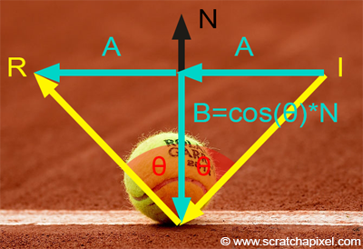
 반사는 위의 코드처럼 심플합니다. 오른쪽 상단의 그림처럼 입사각과 반사각이 같다는 점을 이용하여 해당 공식을 유도하게 됩니다. 입사각과 반사각이 같게되면 오른쪽 하단의 그림처럼 표현할 수 있게 되는데요. 여기서 I와 R은 아래와 같이 구할 수 있습니다.

\(\hat{I} = \hat{A} + \hat{B}\)

\(\hat{R} = \hat{A} - \hat{B}\)

여기서 B는 N을 이용해서 아래와 같이 표현할 수 있습니다.

\(\hat{B} = cos({\theta}) * \hat{N}\)

그러면 이렇게 전개가 가능합니다.

\(\hat{I} = \hat{A} + cos({\theta}) * \hat{N}\)

\(\hat{A} = \hat{I} - cos({\theta}) * \hat{N})

\(\hat{R} = \hat{I} - 2cos({\theta}) * \hat{N}\)

I와 N은 방향을 나타내는 값으로 Normalize가 되어있어 스칼라값이 0입니다. 그리하여 아래의 수식으로 치환이 가능해집니다.

\(\hat{R} = \hat{I} - 2(\hat{I}\cdot\hat{N}) \hat{N}\)


 - refract

Vec3f refract(const Vec3f &I, const Vec3f &N, const float eta_t, const float eta_i=1.f) { // Snell's law
    float cosi = - std::max(-1.f, std::min(1.f, I*N));
    if (cosi<0) return refract(I, -N, eta_i, eta_t); // if the ray comes from the inside the object, swap the air and the media
    float eta = eta_i / eta_t;
    float k = 1 - eta*eta*(1 - cosi*cosi);
    return k<0 ? Vec3f(1,0,0) : I*eta + N*(eta*cosi - sqrtf(k)); // k<0 = total reflection, no ray to refract. I refract it anyways, this has no physical meaning
}

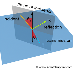
refract는 snell's law에 의해 구현되었습니다.

 우선 \(cos i\)를 확인하여 광선이 매질 안에서 발사되는 것인지를 확인합니다. 만약 \(cos i\)가 0보다 작으면 매질 안에서 발사되는 것이므로 eta_i와 eta_t를 교환해 다시 refract를 진행해줍니다.

 매개변수 중 eta_t는 투과를 진행할 물체의 투과율로 영어로는 ior(index of refraction)라고도 부릅니다. eta_i는 광선이 있는 곳의 투과율입니다.

 snell's law는 refraction을 설명하는 수식으로 다음과 같습니다.


 - fresnel

void Fresnel(const Vector3f &I, const Vector3f &N, const float &ior, float &kr)
{
	float cosi = std::clamp(I.dot(N), -1.f, 1.f);
	float etai = 1, etat = ior;
	if (cosi > 0) { std::swap(etai, etat); }
	// Compute sini using Snell's law
	float sint = etai / etat * sqrtf(std::max(0.f, 1 - cosi * cosi));
	// Total internal reflection
	if (sint >= 1) {
		kr = 1;
	}
	else {
		float cost = sqrtf(std::max(0.f, 1 - sint * sint));
		cosi = fabsf(cosi);
		float Rs = ((etat * cosi) - (etai * cost)) / ((etat * cosi) + (etai * cost));
		float Rp = ((etai * cosi) - (etat * cost)) / ((etai * cosi) + (etat * cost));
		kr = (Rs * Rs + Rp * Rp) / 2;
	}
}


Result


References

www.scratchapixel.com/lessons/3d-basic-rendering/introduction-to-shading/reflection-refraction-fresnel


Introduction to Shading (Reflection, Refraction and Fresnel)

Introduction to ShadingReflection, Refraction (Transmission) and Fresnel Reflection and refraction are very common in the real world and can be observed every day. Glass or water are two very common materials which exhibit both properties. Light can pass t

www.scratchapixel.com

github.com/ssloy/tinyraytracer


ssloy/tinyraytracer

A brief computer graphics / rendering course. Contribute to ssloy/tinyraytracer development by creating an account on GitHub.

github.com


출처 : http://answers.unity3d.com/questions/458207/copy-a-component-at-runtime.html


1
2
3
4
5
6
7
8
9
10
11
12
T CopyComponent<T>(T original, GameObject destination) where T : Component
 {
     System.Type type = original.GetType();
     Component copy = destination.AddComponent(type);
     System.Reflection.FieldInfo[] fields = type.GetFields();
     foreach (System.Reflection.FieldInfo field in fields)
     {
         field.SetValue(copy, field.GetValue(original));
     }
     return copy as T;
 }
 
cs


Type.GetFiels

(https://msdn.microsoft.com/ko-kr/library/ch9714z3(v=vs.110).aspx)

 - 현재 타입에서 public 필드를 가져오는 함수입니다. [SerializeField]는 가져오지 않습니다.

Save

1
2
3
4
5
6
7
8
9
10
11
12
13
14
15
16
17
18
19
20
21
22
23
24
25
26
27
28
29
30
31
32
33
34
35
36
37
38
39
40
41
42
43
44
45
46
47
48
// (1) 스크린샷용 카메라를 준비합니다.
screenShotCamera.gameObject.SetActive(true);
 
// (2) 화면 크기를 지정합니다.
Vector2 screenSize = new Vector2(Screen.width, Screen.height);
 
// (3) 저장할 이미지의 크기를 지정합니다.(화면 크기 그대로 저장을 원하면 screenSize로 대체하시면 됩니다.)
Vector2 imageSize = new Vector2(
    cat.pictureSize.x / cameraSize.x * screenSize.x,
    cat.pictureSize.y / cameraSize.y * screenSize.y);
 
// (4) 저장할 이미지의 Offset을 지정합니다.
Vector2 imageOffset = cat.pictureOffset;
imageOffset.x += cameraSize.x * 0.5f - transform.position.x;
imageOffset.y += cameraSize.y * 0.5f - transform.position.y;
 
// (5) OpenGL의 경우 y축이 Upwards이고, 나머지의 경우 y축이 Downwards입니다.
if (SystemInfo.graphicsDeviceType != UnityEngine.Rendering.GraphicsDeviceType.OpenGL2 &&
    SystemInfo.graphicsDeviceType != UnityEngine.Rendering.GraphicsDeviceType.OpenGLCore &&
    SystemInfo.graphicsDeviceType != UnityEngine.Rendering.GraphicsDeviceType.OpenGLES2 &&
    SystemInfo.graphicsDeviceType != UnityEngine.Rendering.GraphicsDeviceType.OpenGLES3)
    imageOffset.y = cameraSize.y - imageOffset.y;
 
imageOffset.x *= screenSize.x / cameraSize.x - imageSize.x * 0.5f;
imageOffset.y *= screenSize.y / cameraSize.y - imageSize.y * 0.5f;
 
// (6) RenderTexture에 screenShotCamera가 보고 있는 화면을 Render 합니다.
RenderTexture rt = new RenderTexture((int)screenSize.x, (int)screenSize.y, 32);
screenShotCamera.targetTexture = rt;
screenShotCamera.Render();
RenderTexture.active = rt;
 
// (7) RenderTexture를 Texture2D로 옮깁니다.
Texture2D cache = new Texture2D((int)imageSize.x, (int)imageSize.y, TextureFormat.ARGB32, false);
cache.filterMode = FilterMode.Bilinear;
cache.ReadPixels(new Rect(imageOffset, imageSize), 0, 0);
 
// (8) 저장합니다.
byte[] bytes = cache.EncodeToPNG();
string filename = Application.persistentDataPath + "/filename.png";
System.IO.File.WriteAllBytes(filename, bytes);
 
// (9) 뒷정리합니다.
screenShotCamera.targetTexture = null;
RenderTexture.active = null;
Destroy(rt);
screenShotCamera.gameObject.SetActive(false);
 
cs
  1. 스크린샷 카메라를 준비합니다. MainCamera를 사용해도 무방하다면 MainCamera를 사용합니다.
  2. 화면 크기를 지정합니다.
  3. 저장할 이미지의 크기를 지정합니다. (특정 영역을 저장할 때 사용합니다. 그것이 아니라면 화면 크기와 동일하게 지정합니다.)
  4. 저장할 이미지의 Offset을 지정합니다.
  5. 참고 : http://chessire.tistory.com/entry/%EB%A0%8C%EB%8D%94%ED%85%8D%EC%8A%A4%EC%B3%90-%EC%A2%8C%ED%91%9C%EA%B3%84Render-Texture-coordinates
  6. RenderTexture에 screenShotCamera가 보고 있는 화면을 Render 합니다.
  7. RenderTexture를 Texture2D로 옮깁니다.
  8. 저장합니다.
  9. 뒷정리합니다.


Load

1
2
3
4
5
byte[] bytes = System.IO.File.ReadAllBytes(Application.persistentDataPath + "/filename.png");
Texture2D texture = new Texture2D(1, 1, TextureFormat.ARGB32, false);
texture.filterMode = FilterMode.Bilinear;
texture.LoadImage(bytes);
Sprite sprite = Sprite.Create(texture, new Rect(0, 0, texture.width, texture.height), new Vector2(0.5f, 0.5f));
cs


참고 : http://docs.unity3d.com/Manual/SL-PlatformDifferences.html


문제

오늘 스크린샷 기능 만들다가 Unity RenderTexture의 이상한 점을 발견했습니다.


바로 그래픽스 sdk에 따라 Coordinate system이 다르다는 사실...

참고 URL을 가보시면 이런 글을 확인하실 수 있습니다.


해결방법


1
2
3
4
5
if (SystemInfo.graphicsDeviceType == UnityEngine.Rendering.GraphicsDeviceType.OpenGL2 ||
    SystemInfo.graphicsDeviceType == UnityEngine.Rendering.GraphicsDeviceType.OpenGLCore ||
    SystemInfo.graphicsDeviceType == UnityEngine.Rendering.GraphicsDeviceType.OpenGLES2 ||
    SystemInfo.graphicsDeviceType == UnityEngine.Rendering.GraphicsDeviceType.OpenGLES3)
 
cs

위 조건일 때, y값을 반전시켜주시면 됩니다.

C++에서 C#함수를 호출하는 방법에 대해 포스팅하겠습니다.(곁다리로 C#에서 C++함수 호출하는 방법도...)


MonoPInvokeCallback를 사용하시면 됩니다.


in C# ↓↓↓

using UnityEngine;
using System.Collections;
using System.Runtime.InteropServices;
using AOT;

public class SomePlugin //어떤 플러그인입니다.
{
    public delegate void SomeCallback( string result ); // c++에서 호출해줄 Callback형입니다.

    public static extern void ConnectCallback (
SomeCallback someCallback); // c#에서 호출할 c++함수입니다.

    public SomePlugin()
    {
        ConnectCallback( SomeFunction ); // 생성자에서 c++함수를 호출합니다.
    }

    [MonoPInvokeCallback(typeof(
SomeCallback))] // 핵심입니다.
    public static void SomeFunction(string result)
    {
        //something...
    }
}


in C++ ↓↓↓

typedef void (*SomeCallback)(const char* result);
SomeCallback someCallback = NULL;

extern "C"
{
    void ConnectCallback(SomeCallback _someCallback) //c#에서 호출할 함수입니다.
    {
        someCallback = _someCallback;
    }
}

void SomeFunction(const char* result)
{
    if( someCallback != NULL )
        someCallback(result);
}


사용법은 함수포인터 쓰듯이 사용하시면 됩니다.다만 native code에서 액세스 할 수 있도록 MonoPInvokeCallback 속성을 적용해줘야합니다.

유니티에서는 비추천하는 방법입니다(함수 포인터가 주소값 접근이라 위험해서 그런건지 뭔지는 모르겠지만요). 추천하는 방법으로는 UnitySendMessage가 있는데 느린 특징을 가지고 있기에 저는 이 방법으로 해결했습니다.


Unity 빌드 시, 유의할 점

  1. Plugins 폴더
    • 빌드를 수행할 때, 자동으로 Plugins폴더 안의 Android, iOS 폴더안에 있는 "특정" 소스파일이나 리소스파일들을 프로젝트에 추가해줍니다. iOS같은 경우는 Header search path까지 연결해줍니다.
    • 문제는 한 프로젝트로 여러가지 빌드(서로 다른 플러그인을 사용하는)를 뽑을 때 문제가 된다는 것! 잘 삭제 해주지 않으면 쓸데없이 용량을 잡아먹게됩니다.(자동화할때 유의해주세요.)
  2. PostprocessBuildPlayer
    • Plugins 폴더에 넣어놓는다고 하더라도 "특정"파일만 넣는 성격때문에 누락되는 파일들이 있습니다. 손으로 넣어주시는 분들은 상관 없지만 자동화할 땐 엄청난 불편함으로 다가옵니다. 그럴때 이것을 사용합니다.(전 모듈로 mod_pbxproj.py를 사용합니다. 엄청 편해요~)
    • 문제는 Assets/Editor폴더 안에 있는 단 한개의 PostprocessBuildPlayer만 실행이 된다는것입니다. 사용할 PostprocessBuildPlayer들을 PostprocessBuildPlayer_*로 이름을 변경한 후, 메인 PostprocessBuildPlayer가 PostprocessBuildPlayer_*를 전부 찾아 실행해주면 됩니다.
    • 말로하니 복잡하네요. 아래의 소스코드를 참고해주세요.
===========================================================================

#!/usr/bin/python


import sys

import subprocess

import glob

import os


def main(argv):

    paths = glob.iglob( 'Assets/Editor/PostprocessBuildPlayer_*' )


    for path in paths:

        if os.path.splitext(path)[1] != '.meta':

            os.chmod( path, 0755 )

            subprocess.call( [os.path.realpath(path), sys.argv[1], sys.argv[2], sys.argv[3], sys.argv[4], sys.argv[5]] )


if __name__ == "__main__":

    main(sys.argv)

===========================================================================


  • il2cpp
    1. 유니티에서 64bit지원을 위해 부랴부랴 내놓은 아이입니다. il2cpp로 빌드를 하시고 Architecture를 Universial 혹은 ARM64로 설정해 놓아야 64비트 지원이 됩니다.
    2. C#을 빌드하면 나오는 IL파일을 cpp파일로 변환해주는 역할을합니다. Classes 폴더 하위에 Native폴더가 생기네요. 그 안의 파일들을 둘러보긴 했지만... 여하튼 소스가 많이 생겼습니다.
    3. 문제점
      1. 일단 실행파일 용량이 늘어납니다.(소스량이 적다면 조금 늘어나거나 안늘어날 수도 있습니다.) 
      2. 컴파일 시간이 길어집니다.(Unity에서의 컴파일 시간은 의외로 느리지 않은데 xcode에서 빌드시 cpp파일을 전부 빌드해줘야하기 때문에 그로인해 컴파일 시간이 길어집니다.
      3. mono_domain같은 c++에서 c#함수를 가져다 사용할 수 있게해주는 함수를 사용하지 못합니다.
    4. 해결방안
      1. 늘어난 용량은 코드최적화 레벨을 올려주면(ex, strip assembly) 약간 줄어듭니다만 기대치는 낮습니다.
      2. 컴파일 시간은 그냥 감내해야된달까요....
      3. 해당 부분은 유니티에서 권장하는 UnitySendMessage를 사용하면 되지만 느립니다. Object와 함수명을 string으로 찾아서 사용하는 방식이기 때문에 빈번하게 불리는 환경이 아니면 이것을 사용해줍니다.
        1. 빈번하게 사용하는 환경이라면 MonoPInvokeCallback를 사용해줍니다.


 3D를 맨처음 공부하기 전에 꼭 한번 해주면 좋은 실습이 하나 있다. 그것이 바로 랜더링 파이프라인을 API로 직접 구현해 보는 것!!

void LocalSpace(); //물체를 생성

void WorldSpace(); //생성한 물체를 세계에 적용

void ViewSpace(); //세계를 카메라(자신의 시선)에 맞게 재배치

void Culling();  //그려질 것만 추려내고(벽 뒤에 있는 물체나 벽의 뒷면은 그려줄 필요가 없다.)

void Lighting(); //광원효과(빛)을 주고

void Projection(); //원근감을 주기 위해(z축(깊이감)을 적용하는 과정)

void ViewPort(); //보여줄 창의 크기를 잡아주고

void 래터라이즈();

//3D 이미지를 2D로(적용된 z축(깊이)을 x와 y에 적용한다. - 모니터는 x축과 y축밖에 없다.)

void Rendering(); //그림을 그려준다.

일단 이렇게 함수명만 먼저 선언해두고...
행렬클래스(4X4행렬)를 제작하고,
(행렬끼리의 덧셈 뺄셈 곱셈, 행렬과 상수의 곱셈을 operator로 만들어준다. 물론 단위행렬로 만들어주는 함수도 추가해준다.)
3차원 벡터클래스도 제작하고,
(벡터의 외적, 내적 벡터끼리의 곱셈 뻴셈 덧셈, 벡터와 상수의 곱셈 함수도 만들고...)
카메라 클래스는 해골책이네 용책에 나와있는것을 그대로 쓰면된다.

그리고 여러가지 정보를 찾아가면서 함수를 채워넣어가면 된다.

랜더링 하는 방법은 점을 이용해서 API함수에 있는 점을 잇는 함수를 쓰면 됩니다.

컬링이랑 라이트를 뺀 랜더링파이프라인으로 구현한 것이다~!!